
Equipment Introduction
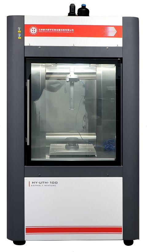
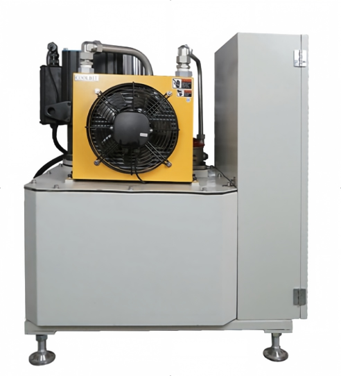
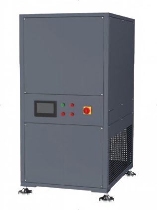
HY -UTM (Universal Testing Machine) is a key equipment in the field of material testing, playing an irreplaceable role in scientific research, industrial production, quality inspection, and many other aspects. The device consists of four parts: the mainframe, hydraulic station, refrigeration unit, and controller. Its basic principle is that, under the power provided by the hydraulic station, the controller controls the flow and direction of hydraulic oil through hydraulic valves, thereby enabling the piston rod to move according to predetermined pressure and position.
The HY-UTM series, primarily used for testing the mechanical properties of asphalt mixtures, mainly employs three testing methods:
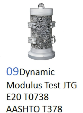
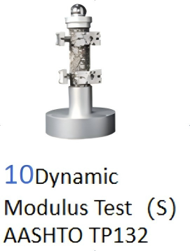
(1) Dynamic modulus tests, represented by AASHTO T378 and JTG E20-T0738, are characterized by automatic switching between various loading frequencies. During the test, the loading amplitude is automatically adjusted based on the set strain range. Upon completion, the test results, such as dynamic modulus and phase angle, are automatically calculated.
(2) Fatigue tests represented by flow value count, tensile fatigue, four-point bending, etc. In such tests, a specific loading wave is generally determined, and under the action of a separate loading frequency and continuous loading cycles, the test continues until the specimen is damaged. After the test concludes, the corresponding test results are automatically provided.
(3) Strength tests represented by SCB, beam bending, and penetration tests generally involve loading at a specified speed or force until the specimen fails, automatically concluding the test. Upon completion, the corresponding test results are automatically calculated.
Hydraulic Station
1、Driven by a servo motor and centered on the “pump-controlled servo” technology, precise control of flow and pressure is achieved through accurate regulation of the pump’s torque and speed.
2、The servo motor speed can be adjusted according to test requirements. Thanks to its high response frequency and excellent torque characteristics, the hydraulic station can quickly adapt to changes in system load.
3、Remote control and local control switching functions are available (remote control software startup; local controller includes startup and low/high pressure switching functions).
4、The oil tank is equipped with a heating function, allowing preheating of the hydraulic oil in low-temperature environments to accelerate system response and improve test efficiency.
5、Integrated sensors are configured to monitor hydraulic oil temperature in real time. A combined air cooling and heating control system ensures the oil temperature remains within the ideal working range of 40–60°C, optimizing system performance and extending equipment lifespan.
6、Through the synergy of liquid level sensors and low-level alarm functions, the hydraulic system transitions from passive fault response to proactive health management, significantly enhancing operational reliability.
The hydraulic station provides load power for the hydraulic cylinder.In the design of the hydraulic station, a servo motor is used to replace the traditional three-phase motor, featuring a silent design that effectively avoids noise interference with other simultaneous tests.
High-precision filters are added at the inlet and outlet ports to extend the service life of the hydraulic cylinder.
The integrated valve block design simplifies the complexity of the hydraulic circuit.
|
Project |
Parameters |
|
Power |
13.4KW |
|
Flow Rate |
32L/min |
|
Maximum Pressure |
25MPa |
|
Power Supply Requirements |
380V 50Hz |
Host Features
1、Four-column reaction frame structure, stable and highly parallel, effectively preventing load force components from deviating during the loading process.
2、Three-sided transparent window design, allowing convenient observation of internal specimens.
3、The main unit is equipped with an LCD screen for easy adjustment of sensor positions and current measurements.
4、Cold air circulation method. The circulating air flows directly from the top to the bottom, ensuring high efficiency, stability, and uniformity.
5、Two types of force sensors. They enable separate analysis of stress differences in specimens from both ends.
6、Internal dimensions: (840 × 500 × 770) mm, providing convenient operation.
Temperature Control System
Independent temperature control system, which operates based on variable frequency control principles, allowing flexible adjustment of cooling or heating power.Equipped with a color LCD touchscreen for control, during cooling, it precisely adjusts the compressor speed and heating device power according to the difference between the environmental chamber temperature and the set temperature, achieving accurate temperature control, high efficiency, and energy savings.To prevent interference from temperature control system vibrations on test results, the temperature control system and the main unit are connected using flexible materials, effectively isolating vibrations generated during operation from transmitting to the main unit. This ensures the stability of the test environment for samples and the accuracy of test data.
Host Environment Advantages
The host environment chamber adopts an advanced multi-hole directional airflow circulation system, which achieves an optimized ratio of laminar and turbulent flow in three-dimensional space through precisely designed arrayed airflow guide holes and dynamic pressure balancing devices. This innovative design not only eliminates temperature stagnation zones caused by traditional single-point air supply but also dynamically compensates for thermal load variations through a real-time feedback adjustment system, ensuring that the temperature difference between any two points within the chamber remains within ±1°C across the temperature range of -20°C to +80°C.
The environment chamber employs a cold-break method to isolate internal temperature control from the external environment, ensuring temperature stability. The glass door is equipped with a built-in heating device to prevent fogging caused by significant temperature differences between the interior and exterior, which could otherwise affect experimental observation.
Controller Module
The controller module, comprising the data acquisition system and control software, serves as the brain of the entire system. Its stable data acquisition, fully compliant data algorithms, and user-friendly human-machine interface form the control center of the system.
The 4-axis/13-channel control system can simultaneously control 4 actuators and collect data from 13 sensors.
With 16-bit AD conversion accuracy and 8x oversampling technology, it ensures high and stable data acquisition precision.
All test results are automatically calculated, eliminating the need for manual user calculations.
The fixture is equipped with a heterodyne radar transceiver chip, enabling automatic identification of measurement fixtures to prevent test failures caused by software-fixture mismatches.
It supports multiple control modes such as stress, strain, and load retention, with automatic switching capabilities. Suitable for dynamic or static tests, the dynamic control frequency can reach up to 25Hz, and it supports custom waveform outputs like sine waves, square waves, and triangular waves.

Software Design Highlights
1、Real-time monitoring of sensor working status, stop loading under out-of-limit conditions to protect the machine.
2、Automatic identification and matching of sensors required for testing.
3、 Real-time monitoring of data during testing, with fault alarms and cause prompts when values deviate from normal.
4、Data acquisition frequency upgraded to 15KHz.Real-time display of change curves during testing.Possess a complete set of experimental method libraries for direct access.
5、Users can set test parameters independently to meet customization needs.Record original test data for easy data retrieval and analysis.
Test:
Dynamic Modulus Test, Dynamic Modulus Test (Small Specimen), Direct Tension Test,
Direct Tension Test, Flow Number Test, Indirect Tension Test, Indirect Tension Test,
Four-Point Bending Fatigue Test, Compression Fatigue Test,
Marshall Stability Test, Asphalt Mixture Crack Test, Asphalt Mixture Bending Test,
Uniaxial Compression Test,
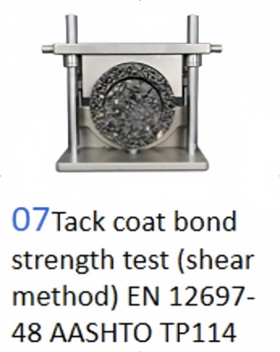
Ideal Rolling Tire Test, Crack Propagation Test (SCB Method), Tack Coat Bond Strength Test (Shear Method), Uniaxial Penetration Test
Introduction to Experimental Fixtures
As needed, select and configure the following fixtures and supporting software.
(Customizable)
Static Test Fixture
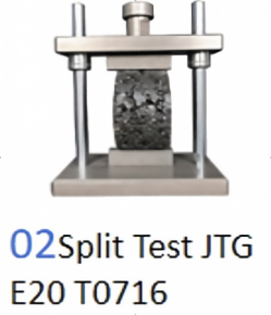
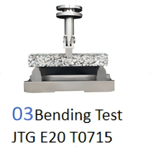
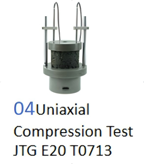
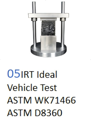

Dynamic Test Fixture
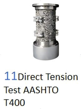
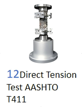
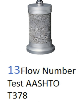
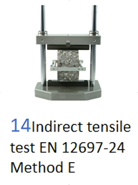

Specimen Bonding Fixture

Test piece bonding fixture

Sensor

Experiment
Dynamic Modulus Test,
Dynamic Modulus Test (Small Specimen),
Direct Tension Test,
Direct Tension Test,
Flow Number Test,
Indirect Tension Test,
Indirect Tension Test,
Four-Point Bending Fatigue Test,
Compression Fatigue Test,
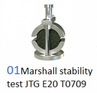
Marshall Stability Test,
Asphalt Mixture Crack Test,
Asphalt Mixture Bending Test,
Uniaxial Compression Test,
Ideal Rolling Tire Test,
Crack Propagation Test (SCB Method),
Tack Coat Bond Strength Test (Shear Method),
Uniaxial Penetration Test
Technical Parameters
|
Model |
HY-UTM-30 |
HY-UTM-100 |
HY-UTM-150 |
|
Actuator Type |
Hydraulic |
Hydraulic |
Hydraulic |
|
Reaction Frame Method |
Four-pillar method |
Four-pillar method |
Four-pillar method |
|
Loading Capacity |
30KN |
100KN |
150KN |
|
Tension |
30KN |
100KN |
150KN |
|
Force Sensor Accuracy |
0.1% |
0.1% |
0.1% |
|
Temperature control method |
External circulation fan |
External circulation fan |
External circulation fan |
|
Loading Method |
Stress/Strain |
Stress/Strain |
Stress/Strain |
|
Control Method |
Personal Computer |
Personal Computer |
Personal Computer |
|
Noise Level |
55~65 decibels |
55~65 decibels |
55~65 decibels |
|
Power Supply |
AC380V 10A |
AC380V 10A |
AC380V 10A |
|
Device Dimensions |
1100X1000X2150(mm) |
1100X1000X2150(mm) |
1100X1000X2150(mm) |
|
Test (see Test List) |
Including all tests in P21 Introduction to Experimental Fixtures |
||
Experimental Features
Dynamic Modulus Frequency Sweep Test –
Significance:
Primarily used to measure the dynamic modulus and phase angle of asphalt mixtures. The dynamic modulus is a performance-related property that can be used for mixture evaluation and characterizing the stiffness of asphalt mixtures.
The phase angle is an important indicator for characterizing the viscoelasticity of materials, serving the mechanistic-empirical pavement design method. In actual pavement, vehicles impose dynamically varying loads.
Through dynamic modulus testing, this dynamic loading condition can be simulated to obtain the mechanical response of materials under real stress states, which more accurately reflects the actual performance of asphalt mixtures compared to static testing.
Key test points:
1. Automatic frequency switching
2. Automatic adjustment of pressure amplitude based on strain range
3. Automatic calculation of test results.

Flow Number –
Significance:
The flow number is a key indicator when studying the permanent deformation characteristics of materials. It is defined as the point where the permanent strain rate reaches a minimum or the cycle number at which the second derivative changes from negative to positive.
Testing Method: By conducting repeated loading tests on the material (such as tests in an asphalt mixture performance tester), the data curve of permanent strain versus load cycle number is recorded. Then, specific algorithms (such as the smoothed central difference algorithm, Francken model, etc.) are used to determine the flow number.

Four-Point Fatigue
Description:
1. The four-point bending fatigue testing machine determines the fatigue life of asphalt mixtures under repeated bending loads under specified test conditions.
2. Two loading waveforms are typically used: half-sine and sine. It is generally believed that moving wheel loads generate stress-strain effects on pavement that approximate a half-sine curve. Therefore, this experimental method adopts the half-sine wave as the standard loading waveform for fatigue testing.
3. The termination condition is when the product of bending modulus and the number of cycles reaches its maximum, or when the stiffness modulus decreases to 50% of the initial bending stiffness modulus.

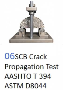
SCB Test
This method uses the Semi-Circular Bending (SCB) technique to determine the fracture energy of asphalt mixtures at room temperature. By analyzing the load-displacement curve obtained from the test, parameters such as fracture energy (Gf) and post-peak slope (m) are calculated to derive the Flexibility Index (FI), which is used to evaluate the crack resistance of asphalt mixtures.
The equipment supports two testing modes:
1. Testing using the main shaft displacement/main shaft load sensor.
2. Testing using the auxiliary shaft displacement/auxiliary shaft load sensor.The software integrates curve fitting algorithms and automatically calculates fracture energy, fracture work, modulus S, and other parameters.

Related Equipment



